CBE DS Powerblock Series
Overview
The CBE DS Powerblock Series is a modular electrical distribution system commonly used in motorhomes and caravans. The system consists of a distribution board and intelligent control panels (such as the PC320 display) that interface via a simple pin-switching and analog signaling interface.
Hardware Architecture
System Components
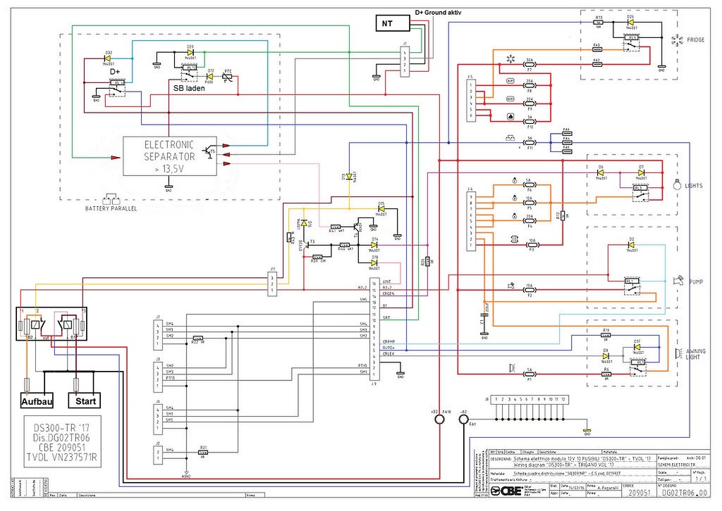
Distribution Board (DS-300)
- Passive electrical distribution with relay-controlled outputs
- 16-pin socket for display connection
- Relays activated by ground switching from display
Control Panel (e.g., PC320)
- Intelligent controller with user interface
- Sends control signals to activate relays on distribution board
- Handles all system logic and user interaction
- Evaluates sensor signals (forwarded from distribution board)
Pin Configuration and Control Interface
The CBE DS Powerblock Series uses a simple electrical interface with no digital communication protocol. All control and monitoring is accomplished through direct pin switching and analog voltage levels.
The connection between the distribution board and the display panel uses a TE Connectivity AMPMODU MOD II 16-pin connector. The connector is a dual-row configuration with 2.54mm (0.1") pitch, compatible with standard MOD II mating connectors. Available variants:
- 280390-2: Right-angle connector
- 280385-2: Straight connector
On the PCB, this socket is designated as J9.
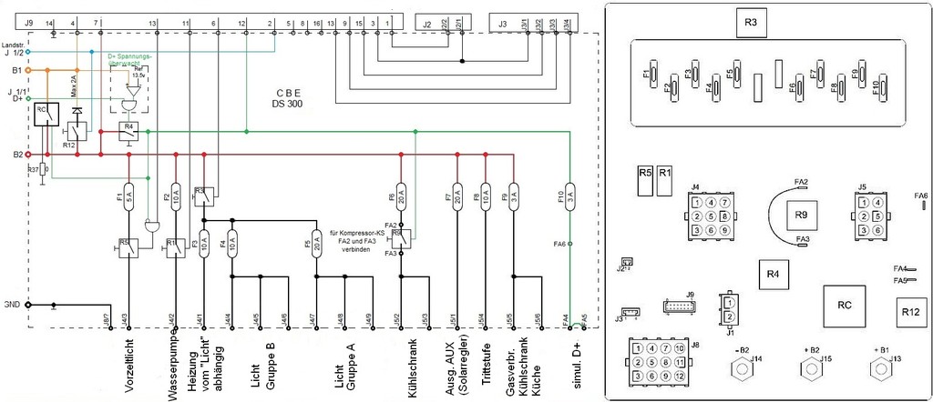

Pinout Table
| Pin | Function | Description |
|---|---|---|
| 1 | TBD | - |
| 2 | Fresh water pin 2 | Fresh water tank sensor |
| 3 | GND | Ground |
| 4 | Fridge relay | Fridge relay control (12V to activate, not ground-switched) |
| 5 | OUT D+ | D+ output (alternator charging signal) |
| 6 | Relay Waterpump | Water pump relay control |
| 7 | Fresh water pin 4 | Fresh water tank sensor |
| 8 | Fresh water pin 3 | Fresh water tank sensor |
| 9 | Grey water pin 2 | Grey water tank sensor |
| 10 | Signal 230V | 230V AC presence signal |
| 11 | AGND (Tank sensors) | Analog ground for tank sensors |
| 12 | 12V+ (B1) | 12V power supply |
| 13 | TBD | - |
| 14 | Main/Lights relay | Main 12V or lights relay control |
| 15 | 12V+ (B2) | 12V power supply |
| 16 | TBD | - |